Reviewed: 12 August 2026. Manufacturer examples often use post centres around common rail or panel lengths, but there is no universal spacing for every fence.
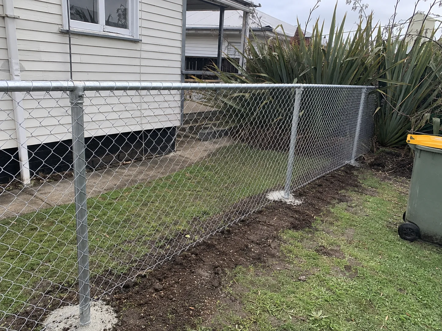
Post spacing is a structural and layout decision. It depends on rail or panel span, fence height and solidity, wind exposure, post and connection size, soil, corners, gates and the tested instructions for proprietary systems. Start with the selected design, then divide the run into practical equal bays.
How to lay out equal bays
Choose a maximum centre-to-centre spacing supported by the design. Divide the clear run by that maximum and round the number of bays up. Divide the run by the resulting bay count. Posts for an isolated straight run equal bays + 1, before adding special gate or corner arrangements.
Illustrative layout: an 18 m run with a design maximum of 2.4 m gives 18 ÷ 2.4 = 7.5, so use 8 bays. Equal centres are 18 ÷ 8 = 2.25 m. That requires 9 line posts/end posts for the isolated run. Do not make seven full bays and leave an awkward short bay unless the system detail intentionally permits it.
| Condition | Why spacing may change |
|---|---|
| Tall solid privacy fence | Greater wind area and connection demand |
| Exposed coastal/ridge site | Higher site wind and corrosion specification |
| Gate opening | Hinge/latch posts carry moving and concentrated loads |
| Corner or end | Loads change direction or terminate |
| Slope | Raking/stepping and panel geometry can limit bay width |
How many palings per metre?
Use the finished cover width, not the nominal board width when palings overlap. For butted/gapped boards: 1,000 ÷ (paling width + clear gap). A 90 mm paling with a 10 mm gap covers 100 mm, giving 10 palings per metre. For 150 mm palings butted tight, 1,000 ÷ 150 = 6.67, so seven are needed to pass one metre; calculate across the full bay and round up. Add a documented cutting/selection allowance rather than blindly adding the same waste percentage to every format.
Manufacturer instructions take priority
Proprietary aluminium, PVC, steel and glass systems have defined panel lengths, post centres, hole sizes and wind limits. Do not substitute a timber rule of thumb. Gate posts and foundations may be larger or deeper than ordinary line posts.
Enter the chosen centres, rails and paling cover in the timber fence calculator. Coordinate spacing with post embedment and measured runs from the fence-length field guide.
Installation references: Mitre 10 NZ fence guide and the selected product manufacturer’s current manual.
Common planning centres—and their limits
For site-built residential timber fencing, 2.4 m centres are a common starting point because they align with common rail lengths and appear in New Zealand project specifications. The Ministry of Education’s school fencing guidance uses approximately 2.4 m centres with minimum 100 × 100 mm timber posts for its preferred close-board specification. That is a project standard, not permission to copy the spacing onto every home.
The current Fencing Act Schedule 2 contains specimen fence descriptions with other maxima—for example, urban post-and-rail posts not more than 2.75 m apart and panel fence posts not more than 2.7 m apart. Those specimen descriptions concern “adequate fence” examples under the Act; they are not a universal structural design table.
Rail span is part of the spacing decision
Rails bridge between posts and carry the palings. Increasing post centres increases rail span and can increase sag, twist and wind load at each connection. Rail size, grade, orientation, number of rails and joint detail must therefore be considered with spacing. A tall close-board fence with two light rails is not equivalent to a low gapped fence with three rails.
Continuous rails may be supplied in lengths that encourage a repeating module, but do not place a weak joint away from appropriate support merely to avoid cutting. Gate, corner and end posts interrupt the regular module and should be laid out first.
End, corner and gate posts are not ordinary intermediate posts
An end post resists the termination of rails and any tensioned element. A corner changes load direction. A gate post carries a moving leaf, hinge forces and repeated impact at the latch. These positions may require a larger section, bracing, closer support or different foundation. Set their exact location before dividing the remaining straight runs.
Worked post-count calculations
Illustrative layout A — 19.2 m straight run at 2.4 m: 19.2 ÷ 2.4 = 8 bays, so the run needs 9 posts including both ends.
Illustrative layout B — 17.5 m run: 17.5 ÷ 2.4 = 7.29, so round up to 8 bays. Dividing 17.5 by 8 gives approximately 2.19 m actual centres and 9 posts. Do not round down to seven bays, which would create 2.5 m spans.
Illustrative layout C — 28 m boundary with a 1 m gate: locate the two gate posts first and treat the fence on each side as separate runs. Subtracting the gate and dividing 27 m as if no opening existed can put intermediate posts in the wrong place.
Slopes and changes of direction
Measure spacing horizontally along each run, then decide whether rails and top line rake with the ground or step. A sharp change of grade may need a post even when the nominal spacing has not been reached, because it creates a new panel geometry. On irregular slopes, shorter bays can reduce awkward paling cuts and excessive steps.
When the layout needs design input
Seek system-specific or professional advice for unusually tall fences, exposed ridges, solid screens, heavy gates, retaining-wall connections, weak or filled ground, commercial security work and any system whose manufacturer publishes fixed panel spans. A 2.4 m rule of thumb is not evidence that posts or foundations are adequate.
From layout to quantities
Enter the actual run lengths and chosen maximum centres in the timber fence calculator. The tool rounds bay counts up and adds end posts, but the user must still add gate, corner and change-of-grade posts correctly. Check embedment separately in How Deep Should Fence Posts Be?, then carry post count, rail count and foundation assumptions into the timber fence cost guide.
References: Ministry of Education Fencing Design Standards and Guidance; Fencing Act 1978, Schedule 2 specimen fences.